PetaLinux
PetaLinux can be built for these reference designs by using the Makefile in the PetaLinux directory
of the repository.
Requirements
To build the PetaLinux projects, you will need a physical or virtual machine running one of the supported Linux distributions as well as the Vitis Core Development Kit installed.
Attention
You cannot build the PetaLinux projects in the Windows operating system. Windows users are advised to use a Linux virtual machine to build the PetaLinux projects.
How to build
From a command terminal, clone the Git repository and
cdinto it.git clone https://github.com/fpgadeveloper/fpga-drive-aximm-pcie.git cd fpga-drive-aximm-pcie
Launch PetaLinux by sourcing the
settings.shbash script, eg:source <path-to-installed-petalinux>/settings.sh
Launch Vivado by sourcing the
settings64.shbash script, eg:source <vivado-install-dir>/settings64.sh
Build the Vivado and PetaLinux project for your specific target platform by running the following commands and replacing
<target>with one of the target design labels found in the build instructions.cd PetaLinux make petalinux TARGET=<target>
The last command will launch the build process for the corresponding Vivado project if that project has not already been built and it’s hardware exported.
Boot from SD card
These instructions only apply to the target boards that allow booting from SD card. This includes all Zynq-7000 boards, Zynq UltraScale+ boards and Zynq RFSoC boards.
Prepare the SD card
Once the build process is complete, you must prepare the SD card for booting PetaLinux.
The SD card must first be prepared with two partitions: one for the boot files and another for the root file system.
Plug the SD card into your computer and find it’s device name using the
dmesgcommand. The SD card should be found at the end of the log, and it’s device name should be something like/dev/sdX, whereXis a letter such as a,b,c,d, etc. Note that you should replace theXin the following instructions.
Warning
Do not continue these steps until you are certain that you have found the correct device name for the SD card. If you use the wrong device name in the following steps, you risk losing data on one of your hard drives.
Run
fdiskby typing the commandsudo fdisk /dev/sdXMake the
bootpartition: typingnto create a new partition, then typepto make it primary, then use the default partition number and first sector. For the last sector, type+1Gto allocate 1GB to this partition.Make the
bootpartition bootable by typingaMake the
rootpartition: typingnto create a new partition, then typepto make it primary, then use the default partition number, first sector and last sector.Save the partition table by typing
wFormat the
bootpartition (FAT32) by typingsudo mkfs.vfat -F 32 -n boot /dev/sdX1Format the
rootpartition (ext4) by typingsudo mkfs.ext4 -L root /dev/sdX2
Copy the following files to the
bootpartition of the SD card: Assuming thebootpartition was mounted to/media/user/boot, follow these instructions:$ cd /media/user/boot/ $ sudo cp /<petalinux-project>/images/linux/BOOT.BIN . $ sudo cp /<petalinux-project>/images/linux/boot.scr . $ sudo cp /<petalinux-project>/images/linux/image.ub .
Create the root file system by extracting the
rootfs.tar.gzfile to therootpartition. Assuming therootpartition was mounted to/media/user/root, follow these instructions:$ cd /media/user/root/ $ sudo cp /<petalinux-project>/images/linux/rootfs.tar.gz . $ sudo tar xvf rootfs.tar.gz -C . $ sync
Once the
synccommand returns, you will be able to eject the SD card from the machine.
Boot PetaLinux
Plug the SD card into your target board.
Ensure that the target board is configured to boot from SD card:
PicoZed: DIP switch SW1 (on the SoM) is set to 11 (1=ON,2=ON)
ZC706: DIP switch SW11 must be set to 00110 (1=OFF,2=OFF,3=ON,4=ON,5=OFF)
UltraZed-EV: DIP switch SW2 (on the SoM) is set to 1000 (1=ON,2=OFF,3=OFF,4=OFF)
ZCU10x: DIP switch SW6 must be set to 1000 (1=ON,2=OFF,3=OFF,4=OFF)
ZCU111: DIP switch SW6 must be set to 1000 (1=ON,2=OFF,3=OFF,4=OFF)
ZCU208: DIP switch SW2 must be set to 1000 (1=ON,2=OFF,3=OFF,4=OFF)
Connect one or more M.2 NVMe PCIe SSDs to the FPGA Drive FMC Gen4. Connect the FPGA Drive FMC Gen4 to the FMC connector of the target board.
Connect the USB-UART to your PC and then open a UART terminal set to 115200 baud and the comport that corresponds to your target board.
Connect and power your hardware.
Boot via JTAG
Tip
You need to install the cable drivers before being able to boot via JTAG. Note that the Vitis installer does not automatically install the cable drivers, it must be done separately. For instructions, read section installing the cable drivers from the Vivado release notes.
Warning
If you boot the Zynq-7000, Zynq UltraScale+ or Zynq RFSoC designs via JTAG, you must still
first prepare the SD card. The reason is because these designs are configured to use the SD card to store
the root filesystem. If you boot these designs via JTAG without preparing and connecting the SD card, the
boot will hang during at a message similar to this: Waiting for root device /dev/mmcblk0p2...
Setup hardware
If you are using a Zynq-7000, Zynq UltraScale+ or Zynq RFSoC board, prepare the SD card according to the instructions above and plug the SD card into your target board.
Ensure that the target board is configured to boot from JTAG:
KC705: DIP switch SW13 must be set to xx101 (1-2=DONTCARE,3=ON,4=OFF,5=ON)
KCU105: DIP switch SW15 must be set to xxxx01 (1-4=DONTCARE,5=OFF,6=ON)
VCU118: DIP switch SW16 must be set to x101 (1=DONTCARE,2=ON,3=OFF,4=ON)
PicoZed: DIP switch SW1 (on the SoM) is set to 00 (1=OFF,2=OFF)
ZC706: DIP switch SW11 must be set to 00000 (1=OFF,2=OFF,3=OFF,4=OFF,5=OFF)
UltraZed-EV: DIP switch SW2 (on the SoM) is set to 1111 (1=ON,2=ON,3=ON,4=ON)
ZCU10x: DIP switch SW6 must be set to 1111 (1=ON,2=ON,3=ON,4=ON)
ZCU111: DIP switch SW6 must be set to 1111 (1=ON,2=ON,3=ON,4=ON)
ZCU208: DIP switch SW2 must be set to 1111 (1=ON,2=ON,3=ON,4=ON)
Connect one or more M.2 NVMe PCIe SSDs to the FPGA Drive FMC Gen4. Connect the FPGA Drive FMC Gen4 to the FMC connector of the target board. Instructions for doing this can be found in the Getting started guide.
Connect the USB-UART to your PC and then open a UART terminal set to 115200 baud and the comport that corresponds to your target board.
Connect and power your hardware.
Boot PetaLinux
To boot PetaLinux on hardware via JTAG, use the following commands in a Linux command terminal:
Change current directory to the PetaLinux project directory for your target design:
cd <project-dir>/PetaLinux/<target>
Download bitstream to the FPGA:
petalinux-boot --jtag --kernel --fpga
An explanation of the above command is provided by the petalinux-boot command:
For microblaze, it will download the bitstream to target board, and
then boot the kernel image on target board.
For Zynq, it will download the bitstream and FSBL to target board,
and then boot the u-boot and then the kernel on target
board.
For Zynq UltraScale+, it will download the bitstream, PMUFW and FSBL,
and then boot the kernel with help of linux-boot.elf to set kernel
start and dtb addresses.
UART terminal
You will need to setup a terminal emulator to use the PetaLinux command line over the USB-UART connection. Connect with a baud rate of 115200.
In Windows
You will need to find the comport for the USB-UART in Windows Device Manager. As a terminal emulator, you can use the open source and free Putty.
In Linux
In Linux, you can find the USB-UART device by running dmesg | grep tty. Typically, the device will be
/dev/ttyUSB0 or it could be followed by a different number. To open a terminal emulator, you can use
the following command:
sudo screen /dev/ttyUSB0 115200
Setup the NVMe SSD in PetaLinux
Log into PetaLinux using the username
petalinux. On the first time you boot, you will be forced to choose a password for this user. The password you choose will be required on all future boots, so choose a password that you will remember.Check that the SSD has been enumerated using:
lspci. Without any arguments, you get the output as shown in the image below. Use the-vvargument, to get a more detailed output with the link speed, number of lanes used, etc.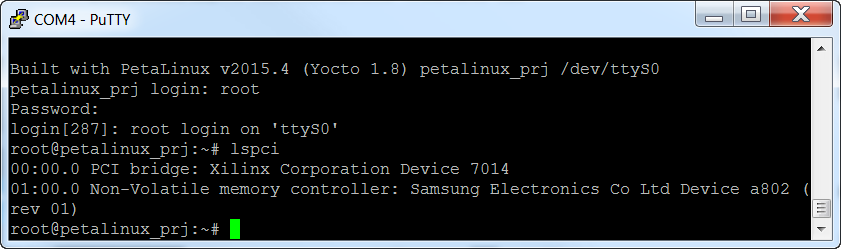
Use lsblk to make sure that the SSD has been recognized as a block device:
lsblk.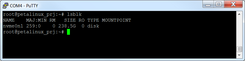
Run fdisk to create a partition on the SSD:
fdisk /dev/nvme0n1.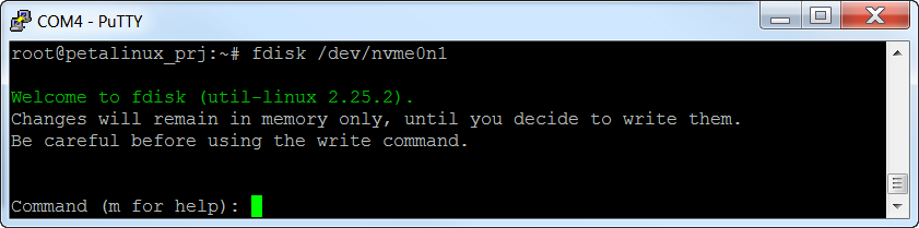
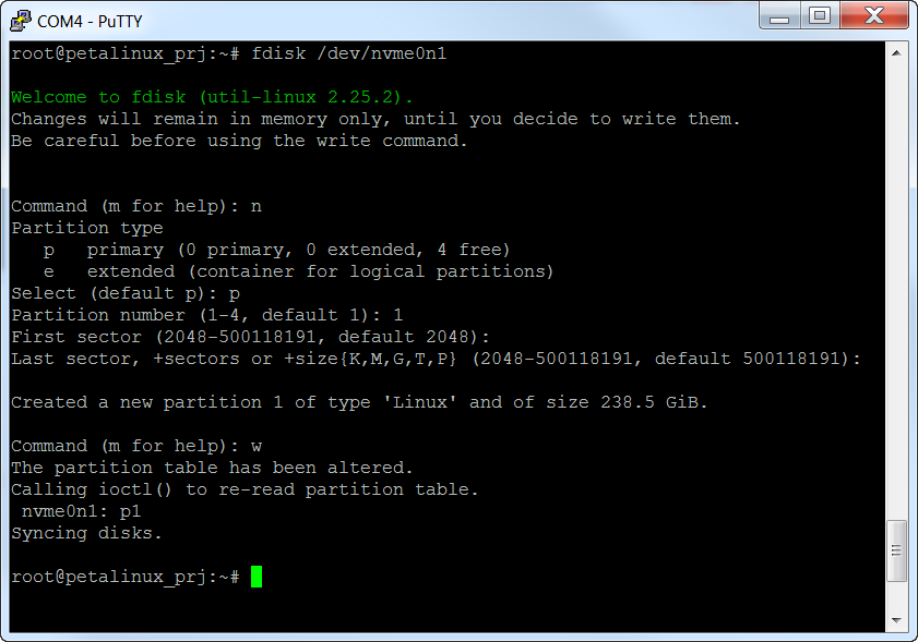
Type these options in fdisk:
Type
nto create a new partitionThen type
p, then1to create a new primary partitionUse the defaults for the sector numbers
Then type
wto write the data to the disk
Get the name of the partition created by running
lsblkagain. In the example below, it isnvme0n1p1.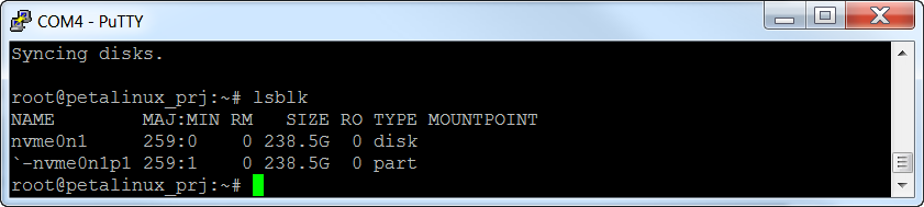
Create a file system on the new partition using:
mkfs -t ext2 /dev/nvme0n1p1.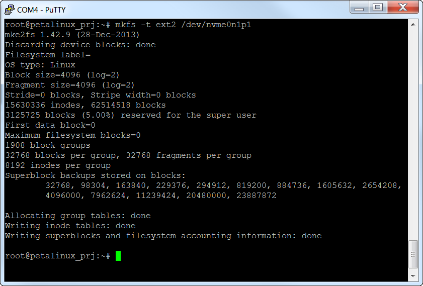
Make a directory to mount the file system to using:
mkdir /media/nvme.Mount the SSD to that directory:
mount /dev/nvme0n1p1 /media/nvme.
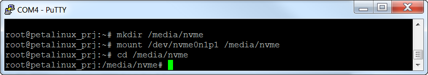
From this point you will be able to access the SSD from the Linux command line.
The SSD will be mounted to the directory /media/nvme. You should be able to copy files to
that directory, create new files, delete files and use all the disk tools that are available in
the PetaLinux build.
Patches and Known Issues
QDMA Root Port Linux Driver Patch
Patch file:
Opsero_QDMA_Bridge_Support_Fixes_for_RC_Linux_Driver_2024_1_32_n_64.patchLocation:
PetaLinux/bsp/<target board>/project-spec/meta-user/recipes-kernel/linux/linux-xlnx/
The Versal projects in this repository contain a patch to the QDMA/XDMA Linux driver. The patch incorporates the fixes from the patch on Answer record AR76647 and it contains two additional changes to the driver:
The “cfg” resource (S_AXI_LITE) is referenced by name, rather than index in the device tree probe function. It is necessary to reference this resource by name rather than by index, because the “reg” property of the device tree contains two resources “cfg” and “bref”, and the order in which they are listed depends on the addresses assigned to them in the Vivado design. The device tree generator lists the one with the lower address first.
Added code to configure the BDF table of the QDMA. Without configuring the BDF table, all transactions on the AXI BAR (S_AXI_BRIDGE) return DECERR (decode error) since the address translation is not being done correctly.
Slave Illegal Burst Errors
The Versal projects in this repository will function correctly however they will produce “Slave Illegal Burst” errors. Below is a snippet of a boot log showing these errors:
[    4.027049] nvme nvme0: pci function 0000:01:00.0
[    4.031809] pci 0000:00:00.0: enabling device (0000 -> 0002)
[    4.037523] nvme 0000:01:00.0: enabling device (0000 -> 0002)
[    4.038983] nvme nvme1: pci function 0001:01:00.0
[    4.045785] tun: Universal TUN/TAP device driver, 1.6
[    4.048058] xilinx-xdma-pcie 80000000.axi-pcie: Slave Illegal Burst
[    4.048077] pci 0001:00:00.0: enabling device (0000 -> 0002)
[    4.059465] xilinx-xdma-pcie 80000000.axi-pcie: Slave Illegal Burst
[    4.059606] CAN device driver interface
[    4.065198] nvme 0001:01:00.0: enabling device (0000 -> 0002)
[    4.071816] usbcore: registered new interface driver asix
[    4.075383] xilinx-xdma-pcie 90000000.axi-pcie: Slave Illegal Burst
[    4.081180] usbcore: registered new interface driver ax88179_178a
[    4.086675] xilinx-xdma-pcie 90000000.axi-pcie: Slave Illegal Burst
[    4.092927] usbcore: registered new interface driver cdc_ether
[    4.099059] xilinx-xdma-pcie 90000000.axi-pcie: Slave Illegal Burst
[    4.105377] usbcore: registered new interface driver net1080
[    4.111246] xilinx-xdma-pcie 90000000.axi-pcie: Slave Illegal Burst
[    4.117568] usbcore: registered new interface driver cdc_subset
[    4.123334] xilinx-xdma-pcie 90000000.axi-pcie: Slave Illegal Burst
[    4.129576] usbcore: registered new interface driver zaurus
[    4.135528] xilinx-xdma-pcie 90000000.axi-pcie: Slave Illegal Burst
[    4.141856] usbcore: registered new interface driver cdc_ncm
[    4.147449] xilinx-xdma-pcie 90000000.axi-pcie: Slave Illegal Burst
[    4.153774] usbcore: registered new interface driver r8153_ecm
[    4.159478] xilinx-xdma-pcie 90000000.axi-pcie: Slave Illegal Burst
[    4.165909] VFIO - User Level meta-driver version: 0.3
[    4.171651] xilinx-xdma-pcie 90000000.axi-pcie: Slave Illegal Burst
[    4.189462] xilinx-xdma-pcie 90000000.axi-pcie: Slave Illegal Burst
[    4.191018] usbcore: registered new interface driver uas
[    4.195783] xilinx-xdma-pcie 90000000.axi-pcie: Slave Illegal Burst
[    4.195790] xilinx-xdma-pcie 90000000.axi-pcie: Slave Illegal Burst
[    4.201149] usbcore: registered new interface driver usb-storage
[    4.207444] xilinx-xdma-pcie 90000000.axi-pcie: Slave Illegal Burst
[    4.213889] i2c_dev: i2c /dev entries driver
[    4.219824] nvme nvme0: Shutdown timeout set to 10 seconds
[    4.227018] usbcore: registered new interface driver uvcvideo
[    4.230468] xilinx-xdma-pcie 90000000.axi-pcie: Slave Illegal Burst
[    4.236251] Bluetooth: HCI UART driver ver 2.3
[    4.241846] xilinx-xdma-pcie 90000000.axi-pcie: Slave Illegal Burst
This is a known issue of Vivado 2024.1 and will be fixed in a future release. AMD has a tactical patch for this issue that requires
copying patch files to your Vivado installation and it is not included in this project repository. As a tactical patch, we are not allowed to share it; you must request a copy from your FAE. You can refer to the tactical patch by this name:
AR000036860_Vivado_2024_1_preliminary_rev1. We have tested the patch and can confirm that it corrects the issue.